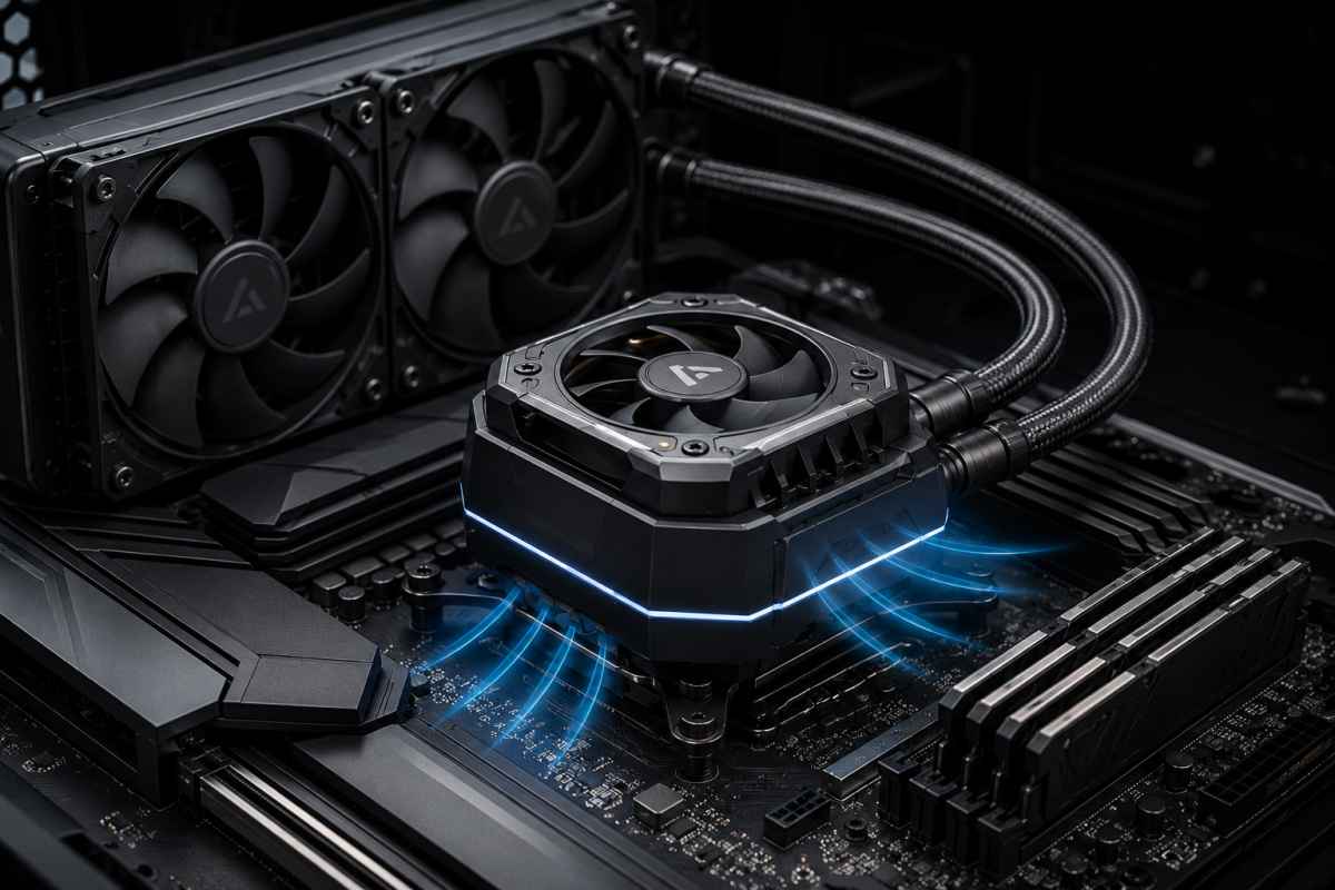


Prototype Concept: Hybrid AIO Water Block With Integrated VRM Fan
Working name – Hybrid Socket-Flow AIO CPU Block
Core principle
The CPU heat is removed through the normal AIO liquid path:
CPU IHS → thermal paste → copper cold plate → microfins → coolant → radiator → radiator fans → room air
1. Water Block Architecture
The block is built as two completely separate systems:
- Liquid cooling system
- Airflow / VRM cooling system
The extra top fan handles the dead zone created when users move from an air tower cooler to an AIO. A tower cooler naturally pushes air around the socket. A standard AIO removes that airflow, so the VRMs can run hotter. Your block fan restores that missing local airflow.
2. Airflow System
Fan position
Small axial fan on top of the water block, centred above the CPU socket.
Possible prototype sizes:
| Fan size | Use case | Notes |
|---|---|---|
| 40 mm | Compact prototype | Easy to fit, but limited airflow |
| 50 mm | Best balance | Better airflow without making block huge |
| 60 mm | Stronger VRM cooling | Larger housing, more noise risk |
| 70 mm | Premium version | Similar to some commercial VRM fan modules |
Why This Can Improve Cooling
AIOs often cool the CPU well but leave the motherboard socket area with less airflow than a tower cooler. That matters most when:
- the CPU draws high power
- the case has poor top/rear exhaust
- the motherboard VRM heatsinks are small
- the radiator is front-mounted as intake
- the user is overclocking
- the GPU dumps heat upward into the socket zone
- the system has low case airflow
The fan on the block adds local airflow where normal AIOs are weak.
Expected improvement
Realistic prototype expectations:
| Area | Expected result |
|---|---|
| CPU core temperature | 0–3°C improvement, maybe none |
| VRM temperature | 5–20°C improvement possible |
| RAM/M.2/socket zone | 2–10°C possible |
| Stability under sustained load | Possible improvement |
| Noise | Could increase if fan is poorly chosen |
| Dust | Will increase around socket area |
The main performance gain:
“Improves socket-area and VRM cooling while retaining AIO CPU cooling performance.”
Better Version Than Existing Designs
Since the basic idea already exists, the prototype needs a point of difference.
Possible improvements:
1. Directional ducting
Most small block fans are fairly general. Your version could use a replaceable directional duct aimed at the hottest motherboard zones.
Example duct options:
AM5 VRM duct
Intel LGA1700 VRM duct
RAM-side duct
M.2-side duct
ITX compact duct
2. Replaceable fan cartridge
Make the fan easy to remove without disturbing the pump.
Magnetic top cover
        ↓
Removable fan cartridge
        ↓
Fixed sealed pump body
This makes cleaning and fan replacement easier.
3. Thermal sensor integration
Add small thermal probes or software support for:
- VRM temperature
- coolant temperature
- air temperature near socket
- pump temperature
4. Offset airflow
Instead of blowing straight down only, use a spiral or radial chamber to force air sideways under pressure.
Fan pushes down
        ↓
Air hits centre deflector
        ↓
Air spreads through four side ducts
        ↓
Air exits toward VRMs/RAM/M.2
5. Low-noise mode
The fan will support zero-RPM or near-silent idle. Corsair’s module, for example, can be configured from 0 RPM up to 3,000 RPM through software
All-in-one liquid coolers have become one of the most popular ways to cool modern desktop CPUs. They move heat away from the processor and into a radiator, where larger fans can exhaust it from the case.
It is a clean, efficient and visually appealing setup, especially for gaming PCs, workstations and high-performance desktop builds.
But AIO liquid cooling has one weakness that often gets overlooked.
When a traditional tower air cooler is installed, its fans push air across the CPU socket area. That airflow does not only cool the CPU heatsink. It also washes over nearby motherboard components, including the voltage regulator modules, chokes, capacitors, memory slots and sometimes the upper M.2 area.
When that tower cooler is replaced with a liquid block, the CPU may run cooler, but the socket area can lose a lot of its local airflow. The radiator fans are now mounted elsewhere in the case. The pump block sits over the CPU, but it usually does not move much air around the motherboard.
That creates an interesting design opportunity: an AIO CPU cooler that combines liquid cooling for the processor with a dedicated fan built into the water block to cool the surrounding motherboard components.
This concept design, called here the Hybrid-Flow AIO, takes that idea further. Rather than simply attaching a small fan to the top of the pump, it uses a more deliberate airflow chamber, ducted exhaust paths and separate control for the pump, radiator fans and socket fan.
The aim is not just to cool the CPU. It is to cool the whole thermal zone around the CPU socket.
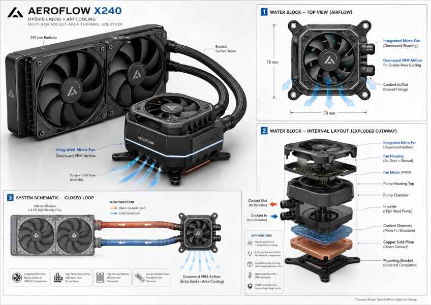
What the Hybrid-Flow AIO Is Designed to Do
The Hybrid-Flow AIO is a liquid CPU cooler with a small fan integrated into the top of the water block. The liquid loop still handles the main CPU cooling job.
Coolant passes through the copper cold plate, absorbs heat from the CPU, travels through the tubes into the radiator and is cooled by the radiator fans.
The difference is the block design.
On top of the pump housing sits a small PWM-controlled fan. This fan draws air from above the CPU block and pushes it into a shaped internal air chamber. From there, the air is directed out through low-mounted vents around the sides of the block.
The airflow is aimed at the areas traditional AIO coolers often ignore:
- motherboard VRM heatsinks
- RAM-side socket area
- upper M.2 heatsink zone
- rear I/O-side power delivery components
- capacitors and chokes around the CPU socket
- stagnant warm air trapped around the pump housing
The result is a hybrid cooling design: liquid cooling for the CPU cores, and direct airflow for the components around the socket.
Why Socket-Area Cooling Matters
Modern CPUs can draw significant power under heavy workloads. Gaming, streaming, rendering, compiling code, running virtual machines and AI-related workloads can all push a system hard for long periods.
When a CPU is under sustained load, the motherboard’s VRM system works hard to deliver stable power. On higher-end boards, VRM heatsinks are usually large enough to manage the heat. On cheaper boards, compact cases or poorly ventilated systems, VRMs can become much hotter than ideal.
A tower air cooler naturally helps by moving air across the board. A standard AIO often removes that airflow. The CPU temperature may look excellent, but the motherboard around it can become warmer.
That does not always cause an obvious problem, but it can matter in several scenarios:
- compact cases with limited airflow
- front-mounted radiators that dump warm air into the case
- high-power CPUs
- overclocked systems
- motherboards with smaller VRM heatsinks
- workstations running long CPU-heavy tasks
- gaming systems where the GPU also heats the socket area
- quiet builds with low case-fan speeds
The Hybrid-Flow AIO is designed to restore some of the airflow that is lost when moving from a tower cooler to a liquid cooler.
How the Water Block Works
The water block has two cooling systems inside one housing.
The first is the sealed liquid-cooling path. This is the part responsible for removing heat from the CPU itself.
The second is the open-air socket cooling system. This is the part responsible for moving air around the motherboard.
The two systems should be mechanically separate. The fan chamber should not interfere with the sealed pump chamber, and the liquid chamber should never need to be opened to clean or replace the fan.
A simplified internal layout would look like this:
Top grille
↓
Small PWM socket fan
↓
Air plenum and directional duct
↓
Pump control PCB
↓
Pump motor
↓
Impeller chamber
↓
Jet plate or flow spreader
↓
Copper microfin cold plate
↓
CPU heat spreader
The CPU cooling process remains conventional:
CPU heat spreader
↓
Thermal paste
↓
Copper cold plate
↓
Microfin coolant channels
↓
Coolant
↓
Radiator
↓
Radiator fans
↓
Case exhaust
The socket airflow process works separately:
Top fan intake
↓
Air plenum
↓
Internal deflector
↓
Four-way ducting
↓
Side and downward exhaust vents
↓
VRMs, RAM area, M.2 zone and socket components
This separation is important. The liquid side needs to be sealed, reliable and pressure-tested. The fan side needs to be serviceable, easy to clean and quiet.
The Integrated Fan Design
The small fan is the most visible part of the concept, but it is not enough by itself. A small fan simply spinning on top of a pump housing may look useful without doing much real work.
The airflow needs to be controlled.
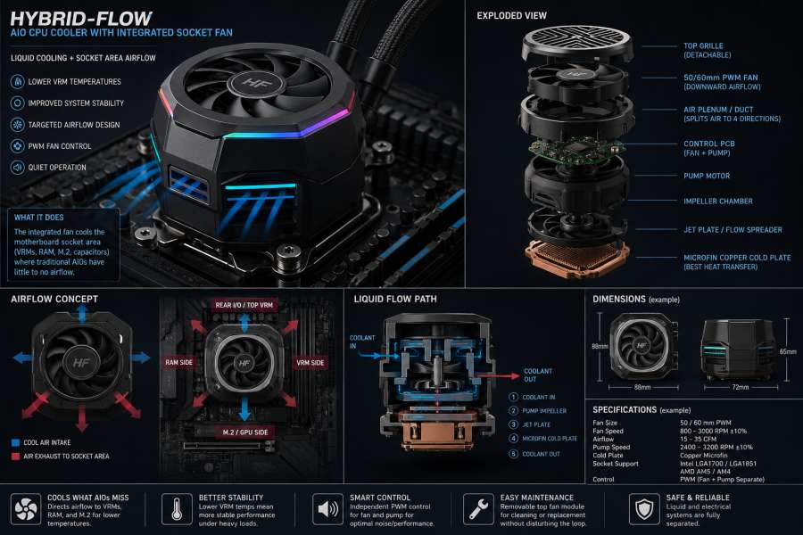
The ideal design uses a 50 mm or 60 mm slim PWM fan mounted above the pump housing. The fan draws air in from the top and pushes it downward into a shaped chamber. A central deflector then spreads the air outward into four duct paths.
Those duct paths send air toward:
- the rear I/O-side VRM area
- the RAM side of the CPU socket
- the main VRM heatsink side
- the upper PCIe/M.2/GPU-side area
The vents should sit low on the block, not high near the decorative top cover. Low-mounted vents help push air across the motherboard surface where the heat-sensitive components actually sit.
A useful design would avoid a simple open grille and instead use directional slots. The goal is to create pressure-guided airflow, not just general turbulence.
Why Ducting Is the Difference
The most interesting part of this concept is not just the fan. It is the ducting.
A poorly designed block fan can create noise, stir hot air and add dust without producing a meaningful temperature improvement. A better design uses the pump housing as an air-distribution body.
The fan pushes air into a small plenum. The plenum then splits that airflow into dedicated channels. Each channel has an outlet shaped to aim air across a specific motherboard zone.
This creates a more purposeful airflow pattern.
- The rear channel can cool the top VRM bank near the rear I/O.
- The side channel can push air across the main VRM heatsink.
- The memory-side channel can move air between the block and RAM slots.
- The lower channel can help move air toward the upper M.2 and GPU backplate area.
This turns the CPU block into a small local airflow hub.
Liquid Cooling Path
The liquid side of the cooler should remain familiar to anyone who has used an AIO.
Coolant enters the block from the radiator, moves through the pump chamber and is forced across the copper cold plate. Inside the cold plate, microfins increase the surface area exposed to the coolant. That allows heat from the CPU to transfer into the liquid more efficiently.
From there, the warmed coolant exits the block and returns to the radiator, where the radiator fans remove the heat.
The basic flow path would be:
Coolant from radiator
↓
Block inlet
↓
Pump impeller chamber
↓
Jet plate / flow spreader
↓
Microfin copper cold plate
↓
Outlet chamber
↓
Tube back to radiator
↓
Radiator cooling
For a prototype, the cold plate should be copper or nickel-plated copper. A microfin design is preferred because it gives the coolant more surface area to collect heat from. The pump chamber should be sealed separately from the fan chamber, with proper gaskets, screws and pressure testing.
What It Could Improve
The main benefit would likely not be a massive reduction in CPU temperature.
That is important to understand.
The CPU is already being cooled by the liquid loop. A small fan above the pump is unlikely to dramatically change CPU core temperatures unless it also helps reduce heat soak around the block or improves case airflow in a small way.
The larger gain is likely to be around the socket area.
A successful design could improve:
- VRM temperatures
- motherboard component temperatures
- local socket airflow
- stability during sustained CPU loads
- airflow in compact or restricted cases
- thermals on boards with modest VRM heatsinks
The likely improvement range would depend heavily on the case, motherboard, CPU power draw and fan speed. In a well-ventilated case with a high-end motherboard, the improvement may be modest. In a compact case or a system with limited airflow, the difference could be more noticeable.
The realistic claim should be:
The Hybrid-Flow AIO is designed to improve socket-area and VRM cooling while maintaining the CPU cooling performance of a traditional liquid AIO.
That is a stronger and more accurate claim than promising huge CPU temperature drops.
Ideal Use Cases
This design would make the most sense for systems where motherboard airflow matters.
Good examples include:
- gaming PCs with high-end CPUs and GPUs
- compact ATX or mATX builds
- small-form-factor systems, if clearance allows
- workstations used for rendering or compiling
- systems running long CPU-heavy workloads
- overclocked or power-unlocked CPUs
- cases with low fan speeds for quieter operation
- builds where the radiator is mounted as a front intake
It would also appeal to PC builders who want a cleaner AIO setup but do not want to give up the motherboard airflow advantage of a tower cooler.
Prototype Design
The smartest way to prototype the idea is not to build a full sealed liquid cooler from scratch.
The first prototype should be a custom fan-and-duct cap mounted on top of an existing AIO pump block. That allows the airflow design to be tested without the complexity and risk of designing a pump, cold plate, seals and coolant loop from the ground up.
A practical prototype would use:
- an existing 240 mm, 280 mm or 360 mm AIO
- a 50 mm or 60 mm slim PWM fan
- a 3D-printed pump-top shroud
- four directional air outlets
- rubber vibration isolation
- a removable top grille
- motherboard PWM fan control
- thermal sensors or a thermal camera for testing
The prototype should be tested with the socket fan turned off and then turned on. That comparison would show whether the design is actually improving the thermal environment around the CPU socket.
Testing the Concept
To prove the design works, testing must focus on more than CPU temperature.
A proper test should measure:
- CPU package temperature
- CPU clock speed
- CPU package power
- VRM temperature
- motherboard temperature
- RAM temperature if sensors are available
- M.2 temperature if nearby
- coolant temperature
- fan RPM
- pump RPM
- room temperature
- noise level
Testing should include idle, gaming, CPU-only load, CPU-plus-GPU load and low-airflow case conditions. The most useful result would be a measurable drop in VRM temperature with no CPU temperature penalty and no unacceptable increase in noise.
The target result should be something like this:
- CPU temperature remains the same or slightly improves
- VRM temperature drops noticeably
- socket-area temperature improves
- fan noise remains controlled
- no interference with RAM, tubing or motherboard heatsinks
A concept like this only becomes valuable if it can prove those results under repeatable testing.
Engineering Challenges
There are several challenges that would need to be solved before this design could become a polished product.
The first is noise. Small fans can become irritating if they spin too fast or sit behind restrictive grilles. A larger 50 mm or 60 mm fan running at lower RPM would likely sound better than a tiny high-speed fan.
The second is dust. A downward-facing socket fan will move dust into an area that is not always easy to clean. A removable fan cartridge or top grille would help.
The third is clearance. A taller pump block may interfere with RAM, motherboard heatsinks, tubes, case panels or GPU backplates. The block must be compact enough to fit a wide range of boards.
The fourth is airflow direction. If the vents are poorly placed, the fan may simply stir warm air around the block. The duct design needs to guide air toward useful thermal zones.
The fifth is serviceability. The fan should be replaceable without disturbing the sealed liquid loop. Users should never have to open the pump chamber just to clean dust from the fan.
How This Concept Could Stand Out
Because some AIO coolers and accessories already include VRM fans, the concept needs a clear point of difference.
The strongest version would not just include a fan. It would include a smarter socket-airflow system.
Possible improvements could include:
- replaceable duct inserts for different motherboard layouts
- directional airflow modules for AM5, LGA1700 and LGA1851 boards
- removable magnetic fan cartridge
- independent PWM control
- zero-RPM idle mode
- VRM-temperature-based fan curves
- coolant temperature monitoring
- tool-free fan cleaning
- low-noise duct geometry
- airflow outlets aimed below the block instead of just around it
That would make the design more than a cosmetic feature. It would become a genuine thermal-management system for the motherboard socket area.
The Air-Assisted Hybrid AIO Cold Plate Design Concept
The CPU cold plate would include small copper heat pipes or a vapour chamber that transfers some heat upward into a fin stack inside the pump housing. The top fan would blow through that fin stack.
How it works
CPU
↓
Thermal paste
↓
Copper cold plate
↓
Coolant microfins remove most heat
↓
Embedded copper heat pipes carry some heat upward
↓
Small fin stack above pump body
↓
Top fan blows across fins
↓
Heat exits into case airflow
Visual block stack
[Top grille]
[50/60 mm PWM fan]
[Mini copper/aluminium fin stack]
[Copper heat pipes or vapour bridge]
[Pump housing / separated air duct]
[Coolant chamber]
[Microfin copper cold plate]
[Thermal paste]
[CPU IHS]
Why this works
The fan is not trying to cool the CPU directly through plastic or dead air. It is cooling a conductive metal structure that is physically connected to the cold plate.
That gives the fan a real thermal path.
Design warning
The heat pipes must not interfere with:
- pump impeller clearance
- coolant chamber sealing
- cold plate flatness
- mounting pressure
- tube fittings
- motherboard clearance
This would be more difficult to manufacture than a simple VRM fan design, but it is technically more interesting.
Option 2: Exposed Cold-Plate Edge With Radial Cooling Fins
This is simpler than heat pipes.
Instead of sending heat upward, the copper cold plate could extend slightly beyond the pump chamber and form a ring of small radial fins around the lower block edge. The top fan would push air down and out through those fins.
How it works
CPU heat
↓
Copper cold plate
↓
Coolant removes most heat
↓
Outer cold-plate rim also warms up
↓
Air passes across radial copper/aluminium fins
↓
Fan removes some extra heat
Side-view idea
       Fan intake
          ↓
   ┌─────────────┐
   │  top fan    │
   ├─────────────┤
   │ air plenum  │
   ├─→ → → → → →─┤
   │ finned ring │  ← attached to cold plate
   ├─────────────┤
   │ cold plate  │
   └─────────────┘
          ↓
         CPU
Advantage
This is easier to prototype because you are not routing heat pipes through the pump body.
Disadvantage
The outer rim of the cold plate will not be as hot as the centre over the CPU die, so the fan’s CPU-cooling impact may be modest.
Realistically, this might give:
| Area | Likely improvement |
|---|---|
| CPU temperature | 1–4°C possible |
| VRM/socket zone | 5–15°C possible |
| Noise risk | Medium |
| Manufacturing difficulty | Medium |
Option 3: Vapour Chamber Cold Plate With Air-Cooled Top Surface
This is the premium version.
Instead of a standard copper cold plate, the CPU contact surface could be part of a flat vapour chamber. The liquid loop cools one side of it, while the fan cools a secondary finned surface connected to the same chamber.
How it works
CPU
↓
Vapour chamber cold plate
↓
Heat spreads across chamber
↓
Coolant removes most heat through microfins
↓
Top-side fin structure removes extra heat by airflow
Why this is attractive
A vapour chamber spreads heat better than a simple copper slab. It could allow both the coolant and fan-assisted fin stack to share heat more evenly.
Problem
This is expensive and far harder to prototype.
It is closer to a commercial R&D design than a garage prototype.
Prototype Stage 1: Finned Cold-Plate Ring
Build a custom cap around an existing AIO block, but add a conductive finned ring attached to the copper cold plate or cold-plate mounting area.
The fan would serve two jobs:
- push air across the finned ring connected to the cold plate
- push remaining airflow outward toward VRMs and motherboard components
Revised airflow
Top fan
↓
Air hits copper/aluminium finned cold-plate ring
↓
Air picks up heat from finned ring
↓
Air exits sideways/downward
↓
Remaining airflow cools VRMs, RAM-side socket area and M.2 zone
This gives the design a real CPU-assisted air-cooling path while keeping the VRM benefits.
Revised Block Architecture
[Top grille / dust guard]
↓
[50/60 mm PWM fan]
↓
[Air plenum]
↓
[Mini fin stack or finned copper ring]
↓
[Air exits through lower side vents]
↓
[Pump motor housing]
↓
[Pump impeller chamber]
↓
[Coolant jet plate]
↓
[Microfin copper cold plate]
↓
[Thermal paste]
↓
[CPU IHS]
The critical addition is this part:
[Mini fin stack or finned copper ring]That component must be physically connected to the copper cold plate, otherwise it will not help cool the CPU.
Best Practical Design
Hybrid Cold Plate With Finned Outer Ring
The cold plate could be designed as one larger copper part:
Top view:

┌─────────────────────────┐
│  finned copper rim       │  ← fan blows across this
│  ┌───────────────────┐  │
│  │ coolant microfins │  │  ← liquid cools CPU hotspot
│  └───────────────────┘  │
└─────────────────────────┘
The centre has microfins for liquid cooling.
The outer area has small fins or thermal contact points for airflow cooling.
Heat path
CPU hotspot
↓
central copper cold plate
↓
coolant microfins remove main heat
↓
remaining heat spreads into copper rim
↓
fan cools finned rim
This is realistic, easier to machine than heat pipes, and gives the fan a legitimate CPU-related purpose.
Stronger Premium Design
Copper Heat Pipe Bridge
A more advanced model could use two or four small flattened copper heat pipes.
Side view:

[fan]
 ↓
[air-cooled fin stack]
 ↑
[flattened heat pipes]
 ↑
[copper cold plate]
 ↑
[CPU]
The heat pipes would carry heat from the cold plate to a small fin stack above the pump housing.
This would let the fan remove heat from the CPU loop more directly.
But there is a catch
The heat pipes need strong thermal contact with the cold plate. They cannot just touch the plastic housing. They need to be:
- soldered
- brazed
- clamped under high pressure
- bonded with high-performance thermal epoxy
Loose contact will make the design perform poorly.
Updated Performance Expectations
If you add a real metal thermal path from the CPU cold plate to the fan-cooled area, then the fan could help slightly with CPU temperatures.
| Design | CPU temp impact | VRM impact | Difficulty |
|---|---|---|---|
| Fan only on block | 0–1°C | 5–20°C | Low |
| Finned cold-plate rim | 1–4°C | 5–15°C | Medium |
| Heat pipes to fin stack | 2–6°C possible | 5–15°C | High |
| Vapour chamber hybrid block | 2–8°C possible | 5–15°C | Very high |
These are prototype expectations, not guaranteed figures.
Cold-Plate Design Summary
The Hybrid Socket-Flow AIO CPU Block combines liquid CPU cooling with an air-assisted cold-plate design, using a block-mounted fan to cool both the motherboard socket area and a secondary metal heat-transfer structure connected to the CPU cold plate.
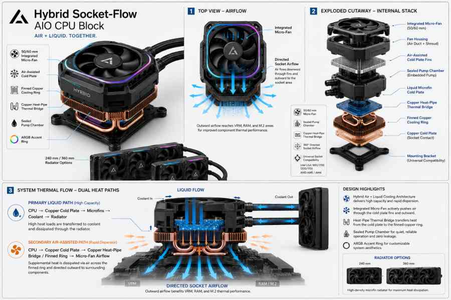
Revised Schematic
For the next image, the design should show three thermal zones:
1. Liquid CPU cooling path
CPU → copper cold plate → microfins → coolant → radiator2. Air-assisted CPU cooling path
CPU → copper cold plate → copper heat pipes / finned ring → top fan airflow3. Socket-area airflow path
Top fan → ducted side vents → VRMs / RAM / M.2 / motherboard componentsBest Version Of The Concept
The best final concept would be:
A 240 mm or 360 mm AIO with a hybrid water block that uses liquid cooling for the CPU, a copper finned ring or heat-pipe bridge for air-assisted CPU heat removal, and ducted side airflow for VRM/socket cooling.
In plain English:
It is not just an AIO with a fan on top. It is a dual-path thermal block: liquid removes the main CPU heat, while the integrated fan cools both a metal CPU-connected heat structure and the surrounding motherboard components.
The Hybrid-Flow AIO Concept Conclusion
The Hybrid-Flow AIO concept is based on a simple but useful idea: modern liquid coolers are good at moving CPU heat to a radiator, but they can leave the motherboard socket area with less airflow than a traditional tower cooler.
By integrating a small, ducted fan into the water block, the cooler can target the parts of the system that standard AIOs often neglect.
The CPU remains cooled by liquid, while the VRMs, RAM-side socket area and surrounding motherboard components receive direct airflow.
The concept is not about replacing radiator performance. It is about fixing the airflow gap that liquid coolers can create around the CPU socket.
For a prototype, the best first step would be a fan-and-duct cap built onto an existing AIO. That would allow real-world testing of VRM temperatures, airflow behaviour, noise and clearance before investing in a fully custom pump and cold-plate assembly.
If the design can reduce socket-area temperatures without adding much noise or complexity, it could become a practical evolution of the modern AIO cooler: not just a CPU cooler, but a more complete motherboard thermal solution.